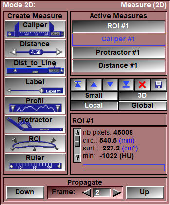
In this mode, you can create and manipulate 2D measurement instruments.
From the Graphic Interface
|
|
|
||||||||||||||
|
Clicking on one of the tools buttons will put the corresponding instrument at the bottom of the current image.
The available instruments are:
|
|||||||||||||||
|
|
|
||||||||||||||
|
|
|
||||||||||||||
|
|
|
||||||||||||||
|
|
|
||||||||||||||
|
|
|
||||||||||||||
|
|
|
||||||||||||||
|
|
|
||||||||||||||
|
Selecting an instrument from this single selection list will change the color of this instrument to red and its information will be displayed in the Information box.
|
|||||||||||||||
|
Top/Up/Down/Bottom |
The instruments are stacked in the order of their creation. You can change that order with these buttons. The order is important: if you have the control points of multiple instruments overlap one another. The control point that will be selected for dragging belongs to the instrument on top.
|
||||||||||||||
|
This button will cause the instrument selected by the Active Measure list to be deleted. If no instrument is selected, this button will be disabled.
|
|||||||||||||||
|
This button will write to a file the values associated with the instrument selected by the Active Measure list. If no instrument is selected, this button will be disabled. The syntax used is the same as the “Save to script” command below.
|
|||||||||||||||
|
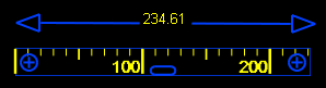
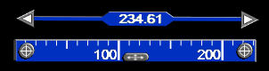
This setting affects the appearance of all instruments. In the “Small” mode, a simple line drawing is used to represent the instruments. In the 3D mode, a more detailed 3D look is given to the instruments.
|
|||||||||||||||
|
This setting will be applied to future instruments. In the local setting, when a new instrument is created, it will only be active in the current image. In the “Global” setting, when a new instrument is created, it will be active in all the images.
|
|||||||||||||||
|
Rename Window
|
You can edit the name of the tool in this window |
||||||||||||||
|
The numerical values from the selected instrument will be displayed here.
|
|||||||||||||||
|
All the measurement tools present on the starting frame will be copied on the target frame. This tool is also described in the "Interface tools" section of the introduction |
From the Display Area
When the tools are created, they will be at the base of the current frame.
The tools can be directly manipulated in the Display Area by clicking and dragging one of their control points. There are two kinds of control points:
|
|
The anchor point
|
The anchor points icons are either an arrow or a circle with a cross. Moving these points will drag the part of the tool that is connected to it.
|
|
|
The drag point
|
The drag point icon is an oval with arrows. Dragging this point will move the complete tool. |
|
|
|
|
|
|
Mouse button |
Function |
|
|
|
|
|
|
Left |
Drag a measurement tool control point |
|
|
Right |
|
|
|
Middle |
|
From the Keyboard
The following keyboard key can be used while in this module:
|
|
|
|
|
|
Key |
Function |
|
|
|
|
|
|
Delete |
If the cursor is over an instrument's control point, then pressing the "Delete" key will delete the instrument. |
From the Command Line
text commands recognized in this module:
Measure: t_measure Delete
Delete all the measurement instrument matching the template "t_measure".
Measure: t_measure Save file_name
Create a script file to re-create all the measurements matching the template "t_measure".
Measure: t_measure Write file_name
Create a text file containing the measures from all the measurements matching the template "t_measure".
Measure: t_frame Caliper name a_x a_y ...
Measure: t_frame Distance name a_x a_y ...
Measure: t_frame Dist_to_Line name a_x a_y ...
Measure: t_frame Profil name a_x a_y ...
Measure: t_frame Protractor name a_x a_y ...
Measure: t_frame ROI name a_x a_y ...
Measure: t_frame Ruler name a_x a_y ...
Create the specified measurement tool named "name" with the parameters "a_x", "a_y" etc on the frame matching "t_frame".
Measure: Propagate [up|down]
Propagate the result from the current frame to the next frame in the group, either up (the default) or down.
|
|
|
Note:
|
|
|