The CUDA VR Sculpt mode
In this mode, you can sculpt the 3D model, in the virtual world, either by marking the voxels with masks, or by directly changing the values of the voxels.
Note:
|
|
|

From the Graphic Interface
|
|
|
|
The software will attempt to show you all the polygons that are potentially affected by the operation using the selected color. |
From the VR Goggles
The Edit VR mode take place inside a VR room, on both walls of this room you can find panels with a reminder of the interface associated with each touch devices.
|
|
|
|
|
|
Dominant hand |
Second hand |

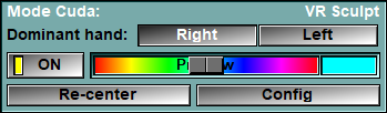
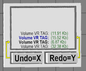
There is also, on the side of your dominant hand, a panel showing some of the volume's parameters. You can summon the VR setup pages by pointing and clicking the "Open Option Menu" with the dominant hand. Also on the other wall you will have an "Undo" menu that enable you to undo/redo any of the last few brush strokes.
|
|
|
|
|
|
Volume's parameters |
Undo/Redo menu |

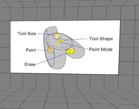
The Dominant Hand
Your dominant hand hold the edition tool, and your other hand is used to grab and move the 3D model. The edition tool can be either a sphere, a disk or a tube.
|
|
|
|
|
|
|
Sphere |
Disk |
Tube |
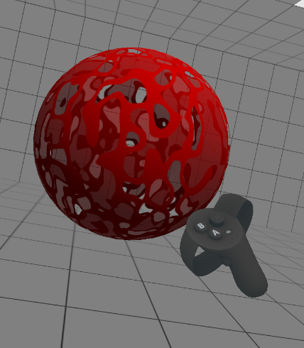


The edition tool can be in one of 6 modes: "Mask -", "Mask +", "GLI -", "GLI +", "Smart" or "Project".
|
Mask - |
In the "Mask -" mode, the tool is red.
•If you press the "Paint" trigger then the mask for all the voxels inside the tool are marked with the flag "Delete". Regardless of the actual voxel value, these voxels will always be considered outside the reconstructed surface. •If you press the "Erase" button, the tool is now in "Erase" mode, and the "Delete" value is removed from mask for all the voxels inside the tool.
|
|
Mask + |
In the "Mask +" mode, the tool is green.
•If you press the "Paint" trigger then the mask for all the voxels inside the tool are marked with the flag "Inside". Regardless of the actual voxel value, these voxels will always be considered inside the reconstructed surface. •If you press the "Erase" button, the tool is now in "Erase" mode, and the "Inside" value is removed from mask for all the voxels inside the tool.
|
|
Grey - |
In the "Grey -" mode, the tool is yellow.
•If you press the "Paint" trigger then the numerical value for all the voxels inside the tool is decreased. •If you press the "Erase" button, the tool is now in "Erase" mode. The index trigger is now used to restore the GLI values to their original (or loaded) value.
In both normal and "Erase" mode, the rate of change of the GLI value of the voxels is controlled by the pressure applied to the index trigger.
The rate of change of the GLI value is also multiplied by the "GLI Factor" from the VR page in the configuration.
|
|
Grey + |
In the "Grey +" mode, the tool is cyan.
•If you press the "Paint" trigger then the numerical value for all the voxels inside the tool is increased. •If you press the "Erase" button, the tool is now in "Erase" mode. The index trigger is now used to restore the GLI values to their original (or loaded) value.
In both normal and "Erase" mode, the rate of change of the GLI value of the voxels is controlled by the pressure applied to the index trigger.
The rate of change of the GLI value is also multiplied by the "GLI Factor" from the VR page in the configuration.
|
|
Smart |
This mode is only accessible is the current mode is "Grey -" and you press the hand trigger.
This mode act like the "Grey -" mode, with the difference that only the voxels whose normal point in the same direction as the painting hand will be affected. This is very handy when you want to remove only one surface. For example, if you have the placenta touching the face of a foetus, you can use this mode to remove only the placenta.
|
|
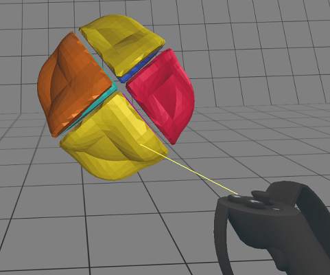
Project |
This mode is only accessible when you select the "Project" tab in the Option Menus. Once selected this mode stay active, even if you exit the Project menu, until you select another mode.
In this mode, all the voxels under the brush that are higher than the threshold value will be projected in the projection direction until the next clip plane.
|
The buttons on the top of the dominants hand control can be used to change the tool mode and the tool's shape. The horizontal movement of the thumb stick can also be used to change the tool's size.
The Other Hand
The second hand controls are used to garb and move the model. Pressing the index trigger will grab the universe, and any movement of the hand will then be applied to the model.
The horizontal movement of the thumb stick is used to scale the model.
The buttons on the top of the interface can be used to activate the "Undo"/"Redo" functions. Each brush stroke of the dominant hand are store in the undo. There is also a button to open the menu page.
The Option Table
To the left of the user there is a table with different measurement tools, an edition sphere and a clip plane frame. The user can select any of these simply by pointing and clicking.
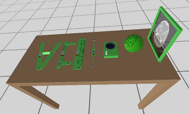
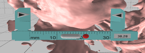
The 4 measurement tools. Each of these tools can have 3 different controls:
|
|
The "arrow": |
It can be "grabbed" by pointing and clicking. Once grabbed, it can be dragged at the desired location. Dragging an arrow will move one section of the tool, all the other arrows will stay at their current location.
|
|
|
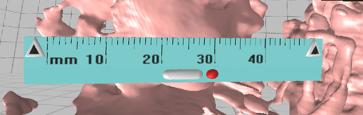
The "Pill": |
This grey cylinder can also be grabbed and dragged, Dragging the pill will move the complete tool
|
|
|
The "Red ball": |
Clicking on the red ball will delete the tool. |
The tools are:
The protractor
The calliper
The ruler
The distance tool.
You can enable/disable or view the measures with the "Measure" menu.
|
|
|
|
|
|


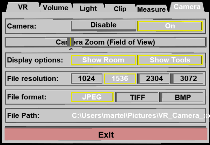
The camera: You can equip your dominant hand with a camera that can be used to make screen grabs. Once equipped, just point and "click". You can also use the thumb stick to control the camera's zoom. There is a page in the interface menu to control the camera's parameters.

The edition sphere: By default, the edition sphere is on, but if you want to remove it from your hands, just click the sphere on the table.
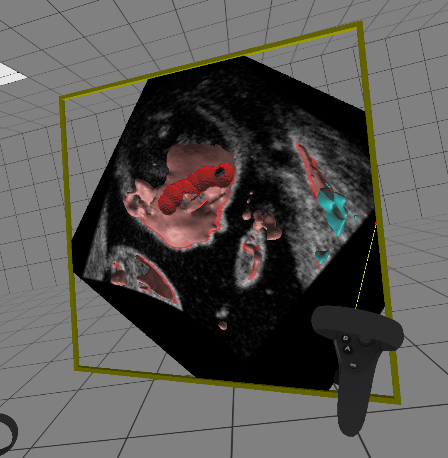
The clipping frame. You can activate this frame from the table. It can then be manipulated by grabbing the frame and moving it. When the frame intersect the data-set's volume it will show a clip plane of the volume. You may want to remove the 3D geometry with the "Mask" menu. You can also control the parameters of the clip plane with the "Clip" menu.
The Option Menus
The option menus can be invoked either by clicking the "Open Option menu" button from the side wall menu, of by pressing the "Option Menu" button on the non-dominant hand controller. You can exit the menus by activating its "exit" button, clicking on the "Close Option Menu" button from the side wall menu, or by pressing the "Option Menu" button on the non-dominant hand controller.
Once the menu is open, the non-dominant hand hold the menu page and the dominant hand is use to point and click on the menu's buttons and sliders.
•Buttons are activated by pointing at them and pressing the index trigger of the dominant hand (the "Paint" trigger).
•Sliders are activated by pointing at them and either pressing the "Paint" trigger or activating the thumb-stick of the dominant hand.. Once a slider is activated it will stay activated as long as the trigger/thumb-stick is activated.
•Color edition boxes have 3 sliders and a demo color box. The 3 sliders can be used to either select the desired red, green and blue (RGB) component of the color, or the hue, light , saturation (HLS). You can toggle between RGB and HLS by activating the demo color box with the "Paint" trigger.
In the "Edit VR" mode, the option menu has 7 pages: "VR","Light", "ROI", "Clean", "Rotation", "Projection" and "Mask". The "VR" and "Light" pages are similar to the pages found in the "Volume VR" mode.
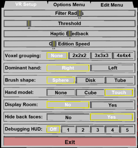
The "VR Setup" menu page
|
|
|
|
Filter Radius |
This is the same value as the one defined in the "Mode Filter" interface. It control the smoothness of the geometry. It can go from 0.5 (anything smaller than 1 is equivalent to "no filter") to 10
|
|
Threshold |
This is the same value as the one defined in the "Mode Threshold" interface.
|
|
Haptic Feedback |
When you either displace or edit the geometry, an haptic feedback is given to each hand with a small vibration. You can control the intensity of this vibration. The range goes from 0 (no vibrations) to 10 (maximum vibration).
|
|
GLI Edition Speed |
When editing in "GLI -" or "GLI +" modes, this value control the influence of the brush. The range goes from 0.5 to 10 on a logarithmic scale.
|
|
Voxel Grouping |
If your graphic card is unable to maintain 90 frames sec. you can reduce the number of displayed voxels by grouping them together. This is also controlled in the "More ROI" interface.
|
|
Dominant Hand |
You can select which is your dominant hand.
|
|
Hand Model |
You an select what geometrical model is used to display your hands. The choices are: a model of the touch devices, a line drawing of a cube, or no models at all.
|
|
Display Room |
You can select whether or not you want to display the surrounding room.
|
|
Hide back Faces |
You can control whether back facing polygons are displayed or not. You will only notice a difference if you put your head inside the model, and even then, it is useful to hide back faces since any bubbles inside the model will become more apparent.
|
|
Debugging HUD |
This will display a series of HUD (Head's Up Displays) giving information on the Oculus VR processing. For more information on these, please refer to Oculus' web pages |
The other menu pages are grouped under 2 tabs of the main menu: The "Option Menu" tab and the "Edit Menu" tab.
The "Option Menu" menu tab
This tab will open a new menu with 5 tabs
The "Light" menu page
|
|
|
|||
|
Light Sources |
You have access to 4 light sources plus the ambient light.
For the ambient light: you can control its color and intensity with the 3 "red", "green" and "blue" sliders.
For the 4 light sources: You can turn them on or off. You can control their position with the "Elevation" and "Azimuth" sliders, and you can control their color and intensity with the 3 "red", "green" and "blue" sliders.
Note:
|
|||
|
Material Presets |
You have a choice of 10 preset materials. Any changes you make to the properties of the currently selected material will be saved to a script if you click the "Save Data Files" option of the "File" menu.
|
|||
|
Material Ambient |
You can control the color of the material that will be affected by the ambient light color.
|
|||
|
Material Diffuse |
You can control the diffuse color of the material
|
|||
|
Material Specular |
You can control both the "shininess" and the color of the specular color of the material. |


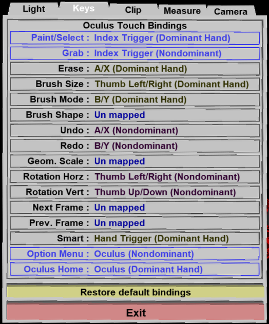
The "Keys" menu page
This page enable you to re-map the hand controler buttons, trigers and joystick controls. Point to the action you want to associate with a control and activate that control.
|
|
|
|
|
|
The "Clip" menu page
This page enable you to modify the behaviour of the clip frame.
|
|
|
|
|
|

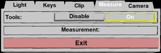
The "Measure" menu page
|
|
|
|
|
|
The "Camera" menu page
|
|
|
The "Edit menu" menu tab
This tab will open a new menu with 6 tabs
The "ROI" menu page
By default, you can edit all the voxels inside a "Volume Box". That box is the bounding box of your geometry. It's dimensions in the 3 main axis are the minimum and maximum dimensions of your geometry. However, if you want, you can use "clipping planes" to limit the region you can edit to a sub-set of that box.
|
|
|
||
|
Clip Planes |
|
||
Reset |
Reset the clipping values to their initial values (min to 0, max to max). The clipping box will be the same as the volume box.
|
||
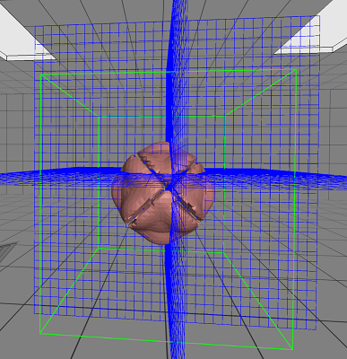
Graphic Options |
By default, the edges of the "volume box" is displayed in blue. All the voxels you can work with are inside this box.
You can enable or disable 2 graphic options:•Clip Lines: Display the edges of the clipping region in green. •Outside Lines: Display the outside lines of the current geometry. If your geometry is Cartesian, then this is the same as the volume box. However, if your geometry is spherical or cylindrical, you will see the outline of the total volume. |
||
|
|
|


The "Clean" menu page
When creating a model from Ultrasound images, there will be a lot of "noise" and undesired surface elements. The "Cleanup" menu allow you to see each individual un-connected surfaces and remove all the ones you do not want.
|
|
|
|
Initiate Cleanup |
The first step in the cleanup process is to compute the different unconnected surfaces. This is done by activating the "Initiate Cleanup" button. Each individual unconnected surface will be displayed with a different color.
After that, you use the dominant hand to point and "select" each surfaces you either want to keep or eliminate.
|
|
Delete |
Activating the "Delete Selected" button will remove all selected surfaces, while the "Delete Un-selected" will keep the selected surfaces and delete all the others. The surface are "removed" by tagging all the voxels used to create them with the "delete" mask.
|
|
Select Color |
You can control the color used to display the selected surfaces. Changing this color will also affect all the "un-selected" surfaces since their color are designed to be different from the selected color.
|

|
|
|
|
|
|
|
|
Initial Volume |
Initiate Cleanup |
Selecting surfaces |
After "Delete Selected" |


The "Rotation" menu page
It is convenient to use the clip planes to create a base plane for your model. However, this base plane will be aligned with the main axis of the volume. And these may not be aligned with your geometry. So it may be convenient to re-align your geometry with the main axis of the volume.
This is what the "Rotation" menu will allow. You align your model by manually positioning it as you which and then activate the "Apply transformation" button to recompute the voxels of the geometry in the new aligned system.
|
|
|
|
Current Rotations |
The X, Y and Z sliders are used to show/control the current rotation. The values are the angles in the Euler system.
|
|
Grid System |
You can rotate the volume 90 degrees in X, Y or Z according the the system of the VR world. This is the system displayed by the 3 orthogonal grids.
|
|
Patient System |
You can rotate the volume 90 degrees in X, Y or Z according the the system of the patient.
|
|
Reset
|
You can reset all rotations to zero. |
|
Apply Transfo |
All the voxels of the volume will be recompute in the grid system.
|
|
Grid Color |
You can control the color of the 3 orthogonal grids used to show the VR main axis. |

|
|
|
|
|
|
|
Using the "Grab" trigger to move the volume |
Using the "Paint" trigger to rotate the viewpoint |
After computing rotation |


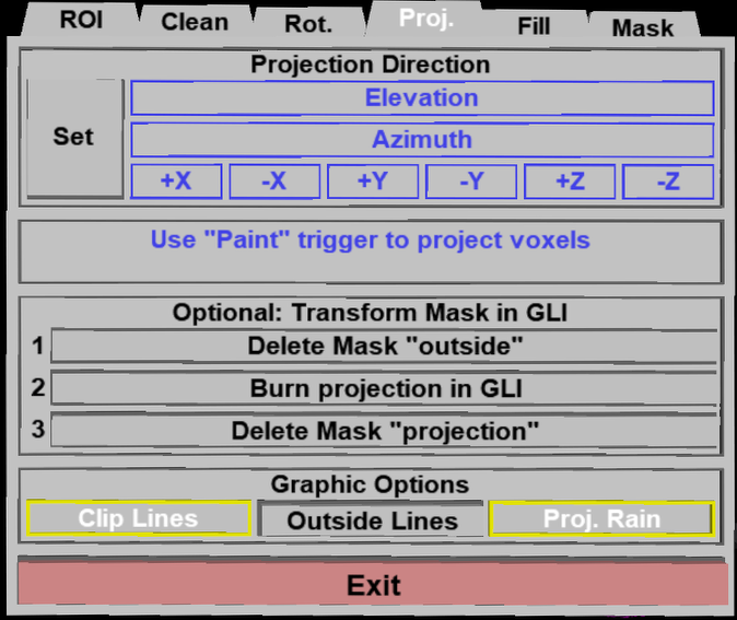
The "Projection" menu page
Once this page is activated, the brush mode is changed to "Projection". When painting with this mode, any voxels that has a GLI value higher than the threshold will be "projected" in the projection direction. All voxels between the source of that projection and the external clip planes will have their mask value set to "Projection". That value has the same effect as the "Fill" mask. All voxels with that mask will be used to create the final geometry.
Since the "Projection" is a mask, the geometry created from it will be rough. If you do not want to have a pronounced "staircase" effect, you need to either project only along the main axis directions (you can use the "Rotation" menu to align the geometry along the main axis) or you can use the "Projection" mask to increase the voxels over the threshold limit using the "Transform Mask in GLI" option.
The "Transform Mask in GLI" option is composed of 3 steps.
Delete the Mask "Outside": GLI values can not be thresholded outside the original volume of the acquisition. If the acquisition was done in a spherical system, a portion of the re-sliced orthogonal volume will be marked as "outside". If you want your projection to affect these voxels, we must first remove this outside" mask.
Burn projection in GLI: In this step, the GLI value of all the voxels that have a "projection" mask will be set to the maximum of their current value or the threshold value. This will insure that all these voxels are considered "inside" the volume. However, the GLI value is subject to the filter. So the actual projection volume will probably "shrink" by the radius of the filter.
Delete Mask Projection: This last step is to insure that the volume is created with the GLI values and not the overwriting mask value.
|
|
|
||||||||||
|
Projection Direction |
|
||||||||||
|
Delete Mask "Outside" |
Delete the bit "Outside" from the mask of all the voxels in the geometry.
|
||||||||||
|
Burn proj. to GLI |
Set the GLI value of all the voxels whose mask contain the bit "Projection" to the maximum of the current value of the threshold value.
|
||||||||||
|
Delete Mask "Proj" |
Delete the bit "Projection" from the mask of all the voxels in the geometry.
|
||||||||||
|
Graphic Options |
|

The "Mask" menu page
Once this page is activated, you can visualize the voxels tagged with the different mask values. The different masks will be shown as line drawing geometries. When you exit this mode, all mask geometries will be hidden and the basic geometry will be displayed. However, the last "Default color" or "Mask color" choice will be used to display the basic geometry.
|
|
|
|
|
Basic Geometry
|
To help see the mask better, you can turn off the basic geometry. You can also select, when the geomtry is displayed, if you use only the default color for it, or if you also color the voxels in contact with a masked voxel.
|
|
|
Mask "Delete" to "Outsize"
|
•The "Show" button is used to toggle the display of the voxels whose mask values contain the desired bit. •The color tool is used to change the default color associated with each of these masks.
Note:
|

The mirror image
A mirror image of what is seen in the VR goggles is displayed in the 3D window of Baby SliceO. Through the configuration interface, you can select if this is a mirror of the left or right eye, or an anaglyph mix of both (you need red/cyan goggles to see this mode correctly).
The graphic speed
To prevent any VR sickness, you should maintain a refresh speed of 90 frames per second. Your refresh speed is displayed in the bottom right corner of the mirror screen.
The program will adapt itself to your graphic card. This process can take a few second during which the refresh will be slower than 90 frames per seconds, but it will eventually stabilize.
If your graphic card is not powerful enough to maintain the refresh speed, you have a few options you can use to try to help:
•You can change the default model use to show your hands from a model of the touch devices, to a simple line drawing cud\be, or even nothing at all. This is changed either with the control interface on the wall of the VR world, or from the VR page in the configuration interface.
•You can stop the program from displaying a mirror image of the VR world in the 3D window. This is changed from the VR page in the configuration interface.
•You can prevent the program from showing you the walls of the VR room. This is changed from the VR page in the configuration interface.
•You can decrease the resolution of the model. This is changed with the vertical motion of the thumb stick of the second hand controls.
From the Display Area
You can use the mouse to move the 3D model in the 3D window, it will also move it in the VR world.
By default, the display area is a mirror of the VR world. It show the image as seen by one of the 2 eyes in the VR goggles. You can change which eye with the "VR" page of the configuration interface or with the key shortcuts. You can also have the program show an amalgam of both eyes. in that case, the display will be an anaglyph that you can see in 3D with red/cyan glasses. In that case you can also control the eye separation using the "b" and "n" keys.
At the bottom of the display you have 3 informations:
•Failed / OK. This tells us if the program was able to display the graphic in the VR goggles. (If you do not wear the goggles, their display is turn off, and the Failed message will be displayed).
•left eye/right eye/anaglyph/off. This tell us the status of the displayed mirror image
•refresh speed. This is the refresh speed of the VR image. You should aim for 90 frames per seconds.
From the Keyboard
The following commands are mapped to keyboard keys as a shortcut:
|
|
|
|
|
|
Key map |
Action |
|
|
|
|
|
|
v |
Change the mirror image (left eye, right eye, anaglyph, off) |
|
|
b / n |
Decrease/increase the eye separation in the anaglyph mode |
|
|
l |
Toggle the VR world box visibility |
|
|
h |
Cycle through 5 modes of HUD display showing VR frame rate statistics |
|
|
p |
Toggle the back face removal mode |
From the Command Line
System Variables defined in this library:
|
|
$VR_BOX |
(U16) |
Flag: 1= VR World Box is displayed |
|
|
$VR_MIRROR |
(U16) |
3D display mirror image: 0=off, 1=right eye, 2=left eye, 3=anaglyph |
|
|
$VR_HANDEDNESS |
(U16) |
Handedness: 0=right hand, 1=left hand |
|
|
$VR_HAND_MODEL |
(U16) |
Displayed hand model: 0=none, 1=box, 2=touch model |
|
|
$VR_HAPTIC |
(U8) |
Haptic interface intensity (0=off to 10=max) |
Commands recognized in this mode:
VR: anaglyph (val|Inc|Dec)
Change the anaglyph red/cyan separation.
VR: box (val|On|Off|Toggle)
If =1, display the VR world box (default=1).
VR: mirror (val|Off|Right|Left|Anaglyph|IInc|Dec)
Status of the mirror image displayed in the 3D window (default=left).
VR: model (val|None|Cube|Touch)
Model use to display the user's hands (default=touch).
VR: handedness (val|Right|Left|Toggle)
Change the user's dominant hand (default=right).
VR: haptic (val|Off|Inc|Dec)
Touch devices haptic feedback intensity (from o to 10) (default=5).
VR: HUD (val|Off|Inc|Dec)
VR statistic HUD. values range from 0 to 5 (default=off)