This class will enable you to mix multiple frames together.
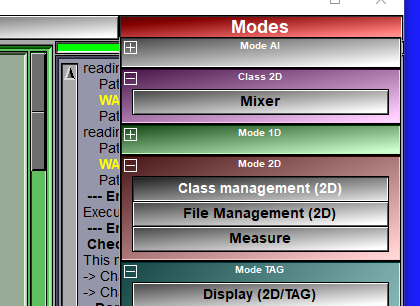
The mixer class is enabled through the 2D Mode: "DB Class management" interface. Once you have an instance of this class in your database tree, a new "Mixer" button will be present in the Modes menu. This button will open the mixer's interface.
|
|
|
|||||
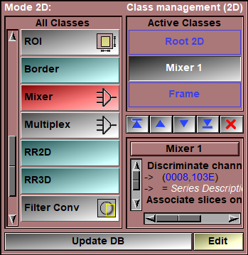
The mixer work by having the frames loaded in sliceOmatic separated in "channels" using a "Discriminate" criteria and then the frames for each of these channels are associated together using the "Associate" criteria. The user has control of the equation used to mix the associated frames together.
The frames in each channels can have different resolution, pixel dimensions and origins. But they must have an overlap. The mixer will only display this overlapped region. This is the case with PET/CT images, the PET usually has a lower resolution that the CT.
Discriminate/Associate
The "Discriminate Channels On" and "Associate Frames On" parameter can be either one (or more) key-words or specific DICOM tags (in the form (xxxx,yyyy)).
For example if you use "series" for the discriminate parameter and "pos" for the associate parameter, then all the frames from the same series will be in the same channels, and all the frames from these series that have the same position will be mixed together.
You can select the discriminate and associate parameters from a pull down menu by clicking the ![]() button or by typing the value in the input window. You can have multiple values, each separated from the other by ";".
button or by typing the value in the input window. You can have multiple values, each separated from the other by ";".
The available key-words that can also be used are:
•"Path" for "File's Path" (The path to the image's file is used).
•"Name" for "File's Name" (The name of the file containing the image is used).
•"ext" for "File's Ext" (The extension of the file's name is used).
•"suffix" for "TAG Suffix" (The suffix of a TAG file's name is used).
•"time" for "Image's Time" (The image study, series or acquisition time is used).
•"org" for "Image's Origin (XY)" (If the x and y origin of 2 images are within 1/4 of a pixel size, they are considered a match).
•"pos" for "Image's Position (Z)" (If 2 images have their "z" position within 1/4 of the slice spacing, they are considered a match).
•"FoR" for "Frame of Reference" (As far as I know, only DICOM identify the FoR, so this is equivalent to (0020,0052)).
•"modality" for "Modality" (The 2 character of the image's modality are used to discriminate/associate the frames).
•"Study" for "Study" (This is an amalgam of: the modality, study ID, study date&time, patient ID and patient name).
•"Series" for "Series" (This is an amalgam of: series number, scan type, series comment (0008,103E), image comment (0020,4000), image sequence position in time for animation files).
•"Image" for "Image number" (image sequence position in a 3D file or (0020,0013)),
•"Acquisition" for "Acquisition number" (equivalent to (0020,0012)).
•DICOM tag (You can enter your desired DICOM tag in the input window)
Note:
|
|
|
If you are unsure of what parameter to use, you can select one and use the ![]() button to see it's value in all the currently selected frames.
button to see it's value in all the currently selected frames.
Here's a few examples:
For MR DIXON or IDEAL images:
Discriminate the channels with the "series" key-word and associate frames with the "pos" key-word. If you have multiple studies at the same time, use "study; pos" for the frame association.
For PET/CT images:
Discriminate the channels with the "modality" key-word and associate frames with the "pos" key-word. If you have multiple studies, use "study; pos" for the frame association. Using the DICOM tag ("slice location" (0020,1041)) instead of the "pos" key-word would probably not work because slices are not exactly aligned.
For images from NIfTI datasets:
You have imported some 3D NIfTI files from a DIXON MR sequence and have one directory per study with each directory contain four files: Images_IP.nii, Images_OP.nii, Images_W.nii and Images_F.nii. Then you will want to discriminate the channels with "Name" and associate the images with "path; Image".
Multi-user comparison:
For repeatability studies, the same GLI image can be copied in different directories, segmented by different users and read back in sliceO. The "Path" parameter can then be used to discriminate each instance of the GLI and an equation like "((T1-T2)>0) ? (T1-T2) : (T2-T1)" can be used to display the difference between each TAG results.
The mixer's equation syntax
The mixer equation is used to specify the value of the pixels "mixed" image. The new pixel values are compute for each pixel of the mixed frames. Depending on the type of the resulting image, you either have one equation (intensity for GLI images) or 3 equations (RGB color components for RGB images) for the pixel values of the image and 1 equation for the TAG values associated with the images. These equations are evaluated for each pixels of the mixed frames each time you click on the "Update DB" button.
The mixer use the following terms:
N is the number of channels available.
Px represent the GLI pixel values of channel x
Tx represent the TAG pixel values of channel x
Rx, Gx, Bx represent the red, green and blue component of the pixels of channel x
MAXx, MINx, represent the maximum and minimum GLI pixel values of channel x
Vx represent the value of slider x
Si, Sj or Sk are used for summations of the following term over the N channels. (Ex: "SiPi / N" is the mean value of the pixels.)
In the previous terms, "x" can be the channel number (1 to N), the character "c" for the channel associated with the TAG value, or one of "i", "j" and "k" if you use a summation.
You can also use constants and sliceO variables in your equation. Ex: $A + P1 * 255
These terms are combined together using the following operators:
|
|
+, -, *, /, % |
Mathematical operators |
|
|
<, >, = |
Test operators |
|
|
&, |, ^ |
Logical operators |
|
|
? |
Conditional operator |
And the functions:
|
|
log, log10, exp, sqrt, abs, sin, cos, tan, asin, acos, atan |
Unary functions |
|
|
min, max, pow, atan2 |
Binary functions |
The mathematical operators
+, -, *, / are the standard plus, minus, multiplication and division operators.
% is the modulo operator, A % B is replaced by the rest in the integer division of A by B. Ex: 5 % 3 = 2
The test operators
A = B replaced by 1 if A equal to B, 0 otherwise
A < B replaced by 1 if A is smaller than B, 0 otherwise
A > B replaced by 1 if A is greater than B, 0 otherwise
The logical operators
| is a logical Or
& is a logical And
^ is a logical Xor
The conditional operator
The syntax is: Test ? A : B
if Test is true then A is evaluated
if Test is false then B is evaluated
The unari functions:
Use a syntax like: "abs(P1)" with 1 argument in parenthesis.
The binari functions:
Use a syntax like: "max(P1,P2)" with 2 comma separated arguments inside the parenthesis.
The sliceOmatic variables (starting with $) can also be used in the equations.
Ex: simple "cross fade" between 2 channels. Mixed pixels = channel 1 if V1=0, channel 2 if V1 = 1
(P1 * (1-V1)) + (P2 * V1)
Ex: Conditional statement with sliceO variable ($A). The resulting pixels are normalized between 0 and 255
( P1 > $A ) ? (P1 / MAX1) * 255 : (P2 / MAX2) * 255
Ex: You can use parenthesis in summations.
Si(Pi-100) is equivalent to (P1-100) + (P2-100) + ... + (PN-100)
Note:
|
|
|
Note:
|
|
|
Note:
|
|
|
Note:
|
|
|
|
|
|
|
|
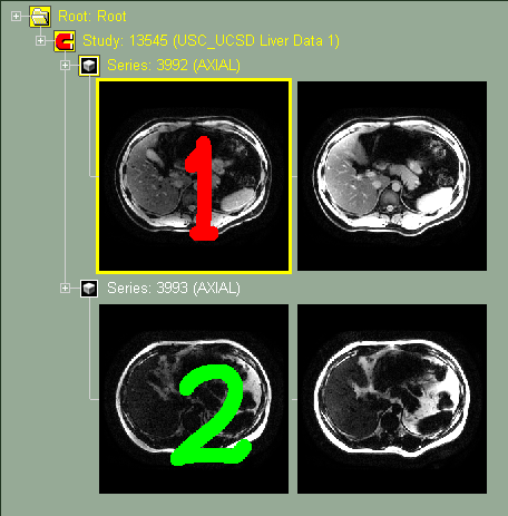
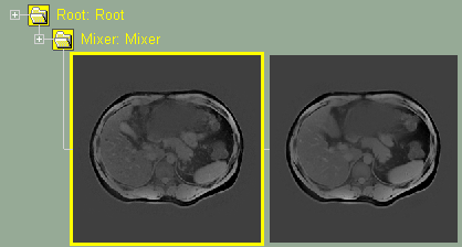
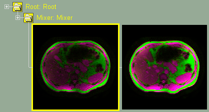
Original images without mixer
|
|
|
|
|
|
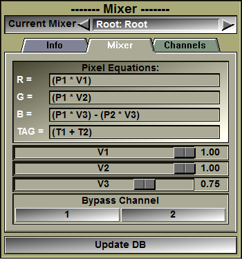
Mixer interface. The 2 channels (Fat & Water) are mixed. |
.png)
From the Graphic Interface
|
|
|
Instance selection |
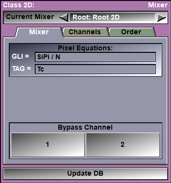
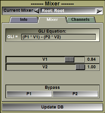
You can have multiple mixers active at the same time in your class tree. Select which of the instances of the class you want to work on.
|
|
Sub-Modes |
The Mixer class interface has 3 sub tabs: Mixer, Channels and Order. Each of these will be explained in more details below.
|
|
Update DB |
Recompute the database tree using the new parameters.
|
|
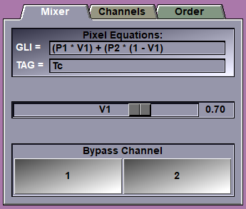
In this interface you can edit the equation used to compute the mixed frame's pixel values. Depending on whether the mixer is in GLI or RGB mode, you can edit the GLI equation, or the 3 RGB equations.
|
|
|
GLI or RGB equations |
You can edit the GLI pixel equation. You must press the "Enter" key to activate your changes. If the equation you enter is invalid, an error message will be displayed in the text window. You either have access to 1 "Grey Level Image" equations, or 3 color component equations depending on the choice made in the "Channels" tab of the interface.
The default equation is the mean value of the pixels of the N channels: "SiPi / N"
|
|
TAG equation
|
You can edit the TAG pixel equation. You must press the "Enter" key to activate your changes. If the equation you enter is invalid, an error message will be displayed in the text window. The resulting TAG values will be clipped to the range 0 to $TAG_Nb.
|
|
Valuator sliders |
Only the sliders used in the equations will be displayed. The sliders can be adjusted from 0 to 1.
|
|
Bypass buttons |
There is one bypass button per channel. Clicking this button will change the equation so that the frames from the selected channel are displayed. It is a quick way to visualize the original frames of each channel.
|
|
|
|
|
|
|||||||||
|
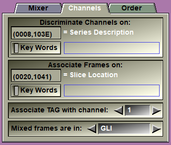
Discriminate |
The value of this parameter decides in which channel the frames from each file will go.
You can select the parameter from a pull-down list using the
The parameter can be a DICOM tag or one of the accepted key-words: "path", "name", "ext", "suffix", "time", org", "pos", for", study", "series", "image", acquisition" or "modality".
DICOM tag are the form (xxxx,yyyy) where "xxxx" is the DICOM group and "yyyy" is the DICOM tag.
In some cases, you may want to discriminate on a specific key-word inside a DICOM tag. You can do this by enable the "Key Words" button, typing the keywords (separated by ";") and pressing "Enter" to activate the filter. You need one key-word for each channels.
|
||||||||
|
Associate |
The value of this tag will be used to match frames across channels.
You can select the parameter from a pull-down list using the
The parameter can be a DICOM tag or one of the accepted key-words: "path", "name", "ext", "suffix", "time", org", "pos", for", study", "series", "image", acquisition" or "modality".
DICOM tag are the form (xxxx,yyyy) where "xxxx" is the DICOM group and "yyyy" is the DICOM tag.
In some cases, you may want to associate frames on a specific key-word inside a DICOM tag. You can do this by enable the "Key Words" button, typing the keywords (separated by ";") and pressing "Enter" to activate the filter. You need one key-word for each association.
|
||||||||
|
TAG to channel |
This parameter decides the channel for the TAG files. If you modify the TAG values, only the images associated with this channel will be modified.
|
||||||||
|
Mix mode |
The mixed frames can be either in "GLI" or "RGB" mode.
In GLI mode, the mixer use one equation to compute a grey level value for the pixels
In RGB mode, the miser use 3 equations to compute the red, green and blue color components of the pixels:
|
|
|
|
|
|
|
|
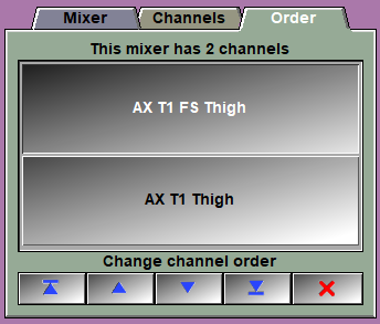
Channel list |
This is a list of all the available channels..
|
|
Channel Order |
The first 4 buttons enable you to change the order of the channels in the mixer. For example if you have an MR IDEAL dataset with in phase (IP) and out of phase (OP) slices, and you want to compute the fat fraction, you will use the equation: n = (IP - OP) / 2IP. In our case if we assume that IP is the first channel, we can us: "(P1 > 0) ? ((P1-P2)/(2*P1)) : 0". But for this to work, we need the in phase to be the first channel! The last button is used to remove from our list any channels we do not use. |
|
|
|
From the Display Area
There is no display area interaction specific to this class.
From the Keyboard
The following commands can also be mapped to keyboard keys as a shortcut:
|
|
|
|
|
|
Key map |
Action |
|
|
|
|
|
|
"SHIFT_1" |
Toggle Bypass mode for channel 1 to 9. |
|
|
to |
|
|
|
"SHIFT_9"
|
From the Command Line
System Variables defined in this library:
|
|
$MIXER_MODE |
(U16) |
|
|
|
$MIXER_EQ_GLI |
(S) |
The GLI pixel equation. |
|
|
$MIXER_EQ_TAG |
(S) |
The TAG pixel equation. |
|
|
$MIXER_EQ_RED |
(S) |
The 3 component pixel equation if the image is in color. |
|
|
$MIXER_EQ_GRN |
(S) |
|
|
|
$MIXER_EQ_BLU |
(S) |
Commands recognized in this library:
Mixer: Mode (GLI|RGB)
Set the current mixer mode. The values are: 0 for GLI and 128 for RGB.
Mixer: Equation (GLI|TAG|Red|Grn|Blu) Equation
Set the one of the equations to the string "equation" (be sure to protect it with quotes).
Mixer: Tag [t_level] channel_id
Set the "Tag" parameter for the different levels of the class. This parameter is used to select which of the channels will have the associated TAG files. The TAG files are accessible by all channels, but when they are saved, the file name is based on the selected channel.
Mixer: Associate [t_level] group element
Set the "Associate" parameter for the different levels of the class.
Mixer: Discriminate [t_level] group element
Set the "Discriminate" parameter for the different levels of the class.
Mixer: Bypass [t_level] [channel] (on|off|toggle)
Set the "Bypass" parameter for the different levels of the channels.
|
|
|